¶ Lower Layer (L1/L2) (Robot Body Coupler)
The Robot Body Coupler is in charge of abstracting away the different possible bodies robots can have. It presents a regular data structure to the middle and possibly higher levels of the system. Some features of this system:
- Abstracts away the robot body
- Fast (Realtime performance) (at least 200Hz loop cycle, best 1kHz)
- Dynamic (future feature)
- Property based
- Because it abstracts away the robot body it permits to execute on a real robot or a simulated one easily
- ROS2 (foxy) compatible
RBC takes the complete urdf of the whole robot as its main input and automatically generates the internal mechanisms to access the robot body hardware driver's data and also builds a "middle" data structure according to a mapping as configured in the URDF. In this way it is possible, as long a common standard is agreed, to define a common interface for the user applications, to access many robots in virtually the same way (from the user perspective. It also makes switching between simulation and a real robot, from the user perspective, almost transparent.
¶ Conceptual diagram:

¶ Implementation example diagram:

¶ Detailed explanation
RBC main program (rbc.py) takes the main urdf robot filename and uses it to generate the mecanisms for connecting and accessing/updating data between the RBC program and the robot drivers. For this a new URDF XML tag is defines "rbc".
A simple example is presented below:
 <joint name="aplator_j0" type="revolute">
    <rbc node="arcoslab_platform_torso">
      <var init="0.0" name="q" topic="arcoslab_platform_torso/state" type="state">
        <msg field="position" field_array="true" index="0" index_type="float" type="impedance_control_msgs.msg.State">

        </msg>
      </var>
      <var init="0.0" name="q_ref" topic="arcoslab_platform_torso/posref" type="cmd">
        <msg field="position" field_array="true" index="0" index_type="float" type="impedance_control_msgs.msg.PosRef">

        </msg>
      </var>
    </rbc>
 </joint>
¶ "rbc" tag
"rbc" tag must be part of each of the joints with data to be accessed. In general, all joints that are not "fixed" should have the "rbc" tag.
"node" attribute allows to configure the name of the ros module of the driver where the information for this joint is taken or accessed.
There can be several "var" sub-tags as part of a "rbc" tag.
¶ "var" sub-tag
¶ Attributes
name="q": allow to create a RBC middle variable to be accessible from the user programs (L1 accesible through "reachers")
init=0.0: allows to give an initial value for the parcular variable
topic="arcoslab_platform_torso/state": ROS2 topic name for accessing this variable data
type="state" (or cmd): This specifies if data is read from the robot or written to the robot. (input or output) (state or command)
¶ "msg" sub-sub tag
attributes:
type: "impedance_control_msgs.msg.State": ROS2 topic message type to read this particular msg.
field="position": In ros messages there is a "field" defined to access a particular data.
field_array=True: Specifies if the field is an array
index=0: the particular position inside the array in case the field is an array
index_type: "float": type of data specified by the field[index]
There can be many "var" sub-tags if there are more variables to be filed with data associated for this particular joint. Each of these var's data can even come from different ros topics. This would be useful for example if for a particular joint, motor data and control comes from a robot arm, but some sensory data (torque sensor) comes from a separated ROS2 driver. Although this sensory data is provided separated from the robot, the sensor could be actually installed inside or attached the robot to a particular joint. RBC allows to integrate this information and presents the result in a very transparent way to the final user.
It is possible to access data from ROS2 message structures that consists of messages inside other messages recursively. RBC permits this message inside message as part of the "msg" sub-sub tag description. For an example of this situation look at our URDF robot file for the wessling hand joints.
¶ Reachers and extenders
Once the "vars" are built by RBC from the URDF description file, its data is filled from the drivers in case the var is "state" type, or its data is feeded to the drivers in case the var is "cmd" type.
"Reachers" can be instantiated to use these "vars". The idea behind reachers is that the reacher wants to control the robot in a certain way and "take it" to a new state: "reach a new state". To the final user they usually present a ROS action interface which accepts a goal and executes the goal until it is reached.
the procedure to instantiate a reacher is exampled with the vectorfield example.
From console:
ros2 service call /sim_humanoid_01/rbc_l2_ctrl rbc_msgs_srvs/srv/RbcL2Ctrl "cmd: 'create_re'
data: 'VF'
name: 'VF0'"
This instantiates a VF. The VF needs a kinematic chain to be defined (as part of the kinematic tree of the robot. (RBC has a kinematic tree instructure inside to be used by the reachers if necessary).
ros2 param set /sim_humanoid_01/VF0 base_link "shoulder"
ros2 param set /sim_humanoid_01/VF0 end_link "wessling_l-hand0-finger0_medial_link"
This creates an OROCOS-KDL (soon an ARCOS-KDL) kinematic chain from end_link to base_link. VF automatically "scans" the tree and finds all the joints inbetween and adds then to this kin chain.
ros2 param set /sim_humanoid_01/VF0 cycle_freq 200.0
Many of the reachers have the notion of a "weight". The VF "outputs" joint velocities to the RBC "q_ref" var (which in turn moves the robot). This velocitier are first multiplied by this "weight". Is a sort of enabler or "mixer" or reachers's data for control vars
ros2 param set --no-daemon /sim_humanoid_01/VF0 weight 1.0
And finally a goal can be sent to the VF:
ros2 action send_goal /sim_humanoid_01/VF0/action rbc_actions/action/VF "goal:
  position:
    x: 0.18
    y: 0.19
    z: 0.82
  orientation:
    x: 0.0
    y: 0.7
    z: 0.0
    w: 0.7
precision:
  linear:
    x: 0.01
    y: 0.01
    z: 0.01
  angular:
    x: 0.01
    y: 0.01
    z: 0.01
timeout:
  sec: 3
  nanosec: 0"
It is possible to create another Vectorfield reacher and they run paralel to each other. The second one could control another arm or finger or both.
Each "reacher" is a separate process spawned from the rbc.py program. All reachers communicate with the "vars" or "control" the robot, using shared memory for maximum performance. The details of how to do this can be seen in a reacher's code.
There are 4 types of reachers and extenders implemented as of now (2021.11.26):
Reachers:
- Vectorfield
- JointReacher
- ExtSimForce
Extenders:
- TouchContact
The difference between an extender and a reacher is that the extender only produces derived or additional state data. For example, the TouchContact extender uses the torques of some joints of the robot, plus Contanct position information given by a user program to estimate the contact wrench on that particular point according to current robot torque readings. This is auxilliary information that user programs can use. It is an "extension" of RBC and the robot's produced data. Reachers command the robot.
In theory, an extender can produce data that can be use by other extenders and reachers. One way is to use ROS2 channels for this, but this is not efficient. Another way is to used shared memory. RBC has a limitation that shared memory data produces by an extender can only be used by other reachers/extenders, if this reachers/extenders were initially instantiated after the extender was instantiated.
¶ Vectorfield reacher
The example above explains the main usage method for this reacher.
This reacher converts cartesian commands (poses: position+orientation) of a particular robot frame to be moved, to joint velocities using a vector field. As the current frame position approaches the goal, the vector field sends weaker velocity commands which allows the robot to reach the goal softly. The vector field takes goals (and possibly obstacles) to generate a cartesian velocity field to take the robot current frame from the current place to the goal according to the field arrows.
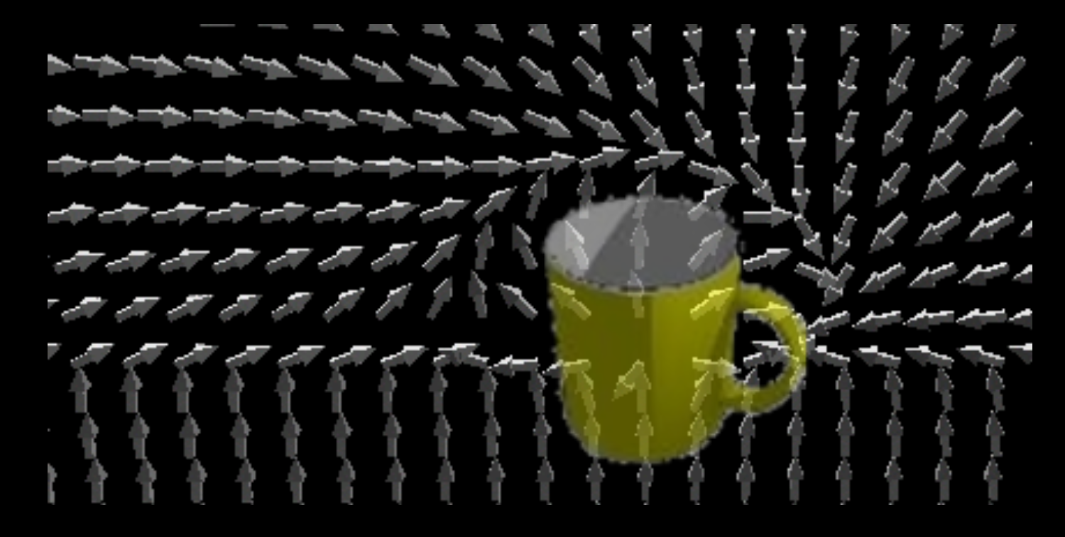
This cartesian velocity command is converted to joint velocities using a weighted damped least square inverse velocity kinematics from OROCOS-KDL (soon ARCOS-KDL).
This reacher avoids the joint limits (which are read from the URDF file by RBC) by modulating the joint weights of the wdls inverse kinematics solver: the weights are reduce proportionally with the distance to the joint limit. At some point the weight becomes zero. The weights are not reduced in case the solver wants to move away from the limit the joint, even if the joint is very near to the limit.
¶ JointReacher reacher
This implements a pid controller in each of the robot joints to be controlled. The joints to be controlled are ros params. They have to by specified before sending goals to this reacher. The goals sent must include only joints that are part of the ros parameter of joints to be controlled. pid values for now are the same to all joints and can be configured on the fly with the ros params facilities.
Usage example:
Create reacher:
ros2 service call /rbc_l2_ctrl rbc_msgs_srvs/srv/RbcL2Ctrl "cmd: 'create_re'
data: 'JR'
name: 'JR0'"
Set command weight:
ros2 param set --no-daemon /JR0 weight 1.0
Set joints to be controlled:
ros2 param set  /JR0 joints --no-daemon "\
- aplator_j0
- aplator_j1
- aplator_j2
"
Send a joint goal:
ros2 action send_goal /JR0/action rbc_actions/action/JointReacher "\
goal:
- joint: "aplator_j0"
  value: 0.0
- joint: "aplator_j1"
  value: 1.0
- joint: "aplator_j2"
  value: 0.7
"
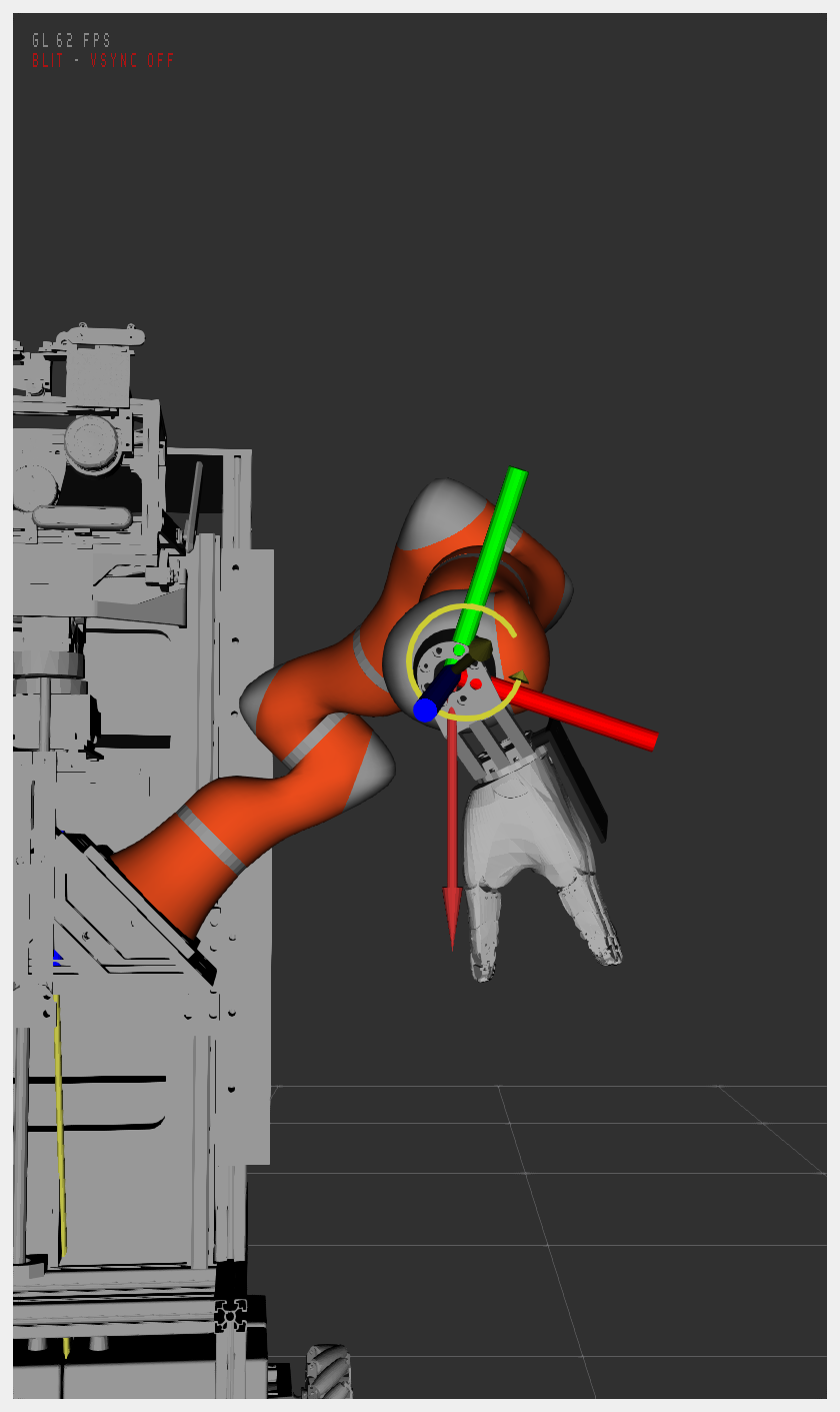
¶ ExtSimForce reacher
This reacher allows a simulated robot to simulate contact events.
This reacher accepts a wrench and a contact position and generates torques that are sent to the "ext_sim_torques" var of RBC. This var is connected on our drivers of a simulated robot parts to simulate for forces on the real world.
It broadcasts a new tranform and frame_id for representing the contact point. It also publishes WrenchStamped data to a topic that can be used to visualize the force using the "wrench" plugin from RViz2. (there is a bug in RViz2 that this wrench plugin crashes Rviz2 from time to time. As of 2025 it seems to be fixed).
Usage example:
Create reacher:
ros2 service call /sim_humanoid_01/rbc_l2_ctrl rbc_msgs_srvs/srv/RbcL2Ctrl "cmd: 'create_re'
data: 'ESF'
name: 'ESF0'"
Set base_link and end_link:
ros2 param set /sim_humanoid_01/ESF0 base_link "shoulder"
ros2 param set /sim_humanoid_01/ESF0 end_link "l_klwr4p_flange_link"
Set the contact point reference frame:
ros2 param set /sim_humanoid_01/ESF0 contact_point_ref "end_link"
Set weigth parameter to 1.0 (to enable robot access):
ros2 param set /sim_humanoid_01/ESF0 weight 1.0
Set a contact force/torque:
ros2 topic pub /sim_humanoid_01/ESF0/touch_contact rbc_msgs_srvs/msg/TouchContact "wrench:
  force:
    x: 0.0
    y: 0.0
    z: -20.0
  torque:
    x: 20.0
    y: 0.0
    z: 0.0
contact_point:
  x: 0.0
  y: 0.0
  z: 0.0"
By setting the "contact_point_ref" to "end_link", means that the contact_point coordinates are relative to the end_link reference_frame.
Beware: the force and torques are always relative or in the "base_link" reference frame.
For visualization
- Add the plugin "Wrench" and select "By Topic" the topic "/humanoid/ESF0/view_wrench"
- Set the following parameters: "Force Arrow Scale: 0.01", "Torque Arrow Scale: 0.01", "Arrow Width: 0.1"
If the plugin crashes, try with "Accept NaN Values"
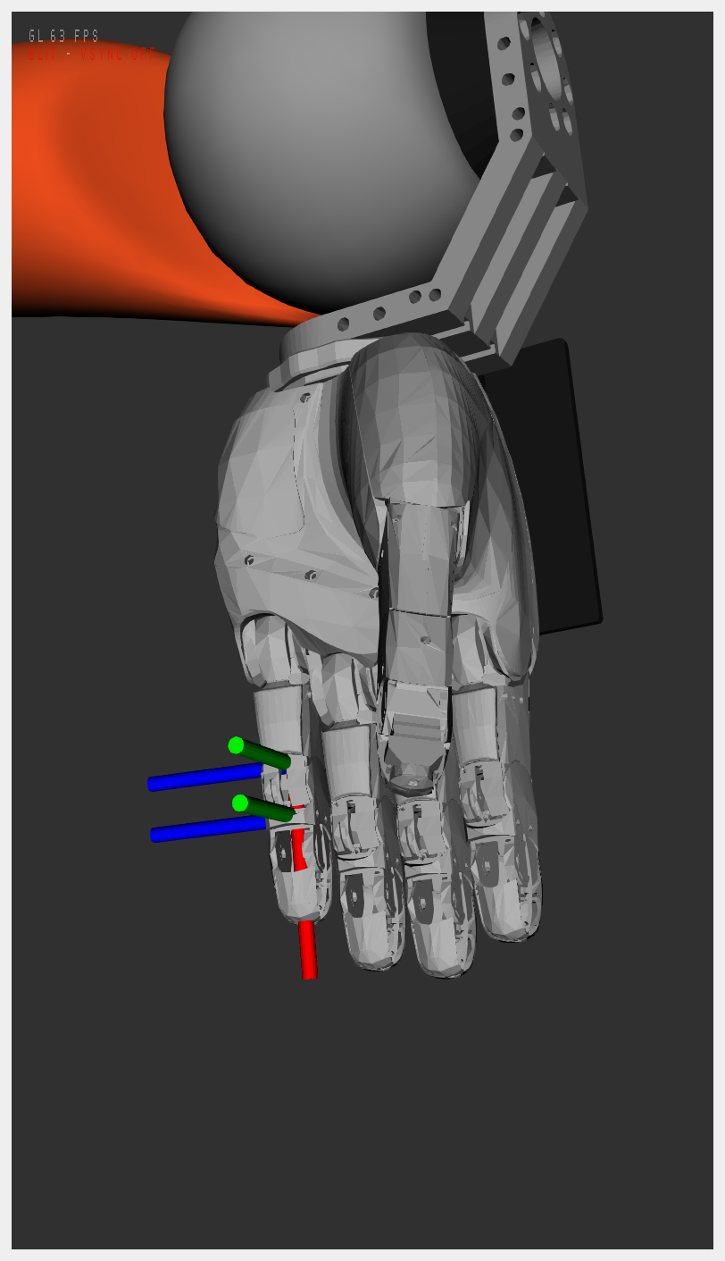
¶ TouchContact extender
This reacher generates contact information from torque sensors on the robot. The user must tell this extender the posible contact position, and then this extender will estimate the contact force at this point according to the current read torques. A kinematic chain can be defined to limit the joints used to generate the estimation.
It broadcasts a new tranform and frame_id for representing the contact point "TCEx_touch". It also publishes WrenchStamped data to a topic "touch_contact_view" that can be used to visualize the force using the "wrench" plugin from RViz2. The extender has a separate parameter for setting a different cycle frequency for the viewer updates (TF and touch_contact_view) than for the touch_contact wrench topic (full speed).
Usage example:
- First create a ExtSimForce reacher for generating a force on the robot
- Use example above
- Use the following force instead of the above one (better for the finger):
ros2 topic pub /sim_humanoid_01/ESF0/sim_touch_contact_in rbc_msgs_srvs/msg/TouchContact "wrench:
  force:
    x: 0.0
    y: -0.5
    z: 0.5
  torque:
    x: 0.0
    y: 0.0
    z: 0.0
contact_point:
  x: 0.02
  y: 0.0
  z: 0.0"
- Then Create a TouchContact extender:
ros2 service call /sim_humanoid_01/rbc_l2_ctrl rbc_msgs_srvs/srv/RbcL2Ctrl "cmd: 'create_re'
data: 'TCE'
name: 'TCE0'"
- Set base_link and end_link parameters:
ros2 param set /sim_humanoid_01/TCE0 base_link "shoulder"
ros2 param set /sim_humanoid_01/TCE0 end_link "wessling_l-hand0-finger4_medial_link"
- Set contact_point (relative to "end_link"):
ros2 param set /sim_humanoid_01/TCE0 contact_point "[0.02, 0.0, 0.0]"
Selecting which sensors to use for force estimation
It is possible to only use a subset of joint sensors for the force estimation. This extender uses a weighted pseudo inverse of the kinematics jacovian for the inverse force kinematics. Using the right side weighted matrix diagonal it is possible to "weigh" the importance of each sensor in the force estimation. Using zero would mean to ignore a particular sensor completely.
For example, to only use the torque sensors on the finger joints use the following command:
ros2 param set /humanoid/TCE0 diag_jweights "[0.0, 0.0, 0.0, 0.0, 0.0, 0.0, 0.0, 1.0, 1.0, 1.0]"
For visualization
- Add the plugin "Wrench" and select "By Topic" the topic "/humanoid/ESF0/sim_touch_contact_view"
- Set the following parameters: "Force Arrow Scale: 0.1", "Torque Arrow Scale: 0.1", "Arrow Width: 0.05"
- Add the plugin "Wrench" and select "By Topic" the topic "/humanoid/TCE0/touch_contact_view"
- Set the following parameters: "Force Arrow Scale: 0.1", "Torque Arrow Scale: 0.1", "Arrow Width: 0.05"
If the plugin crashes, try with "Accept NaN Values"
¶ Examples
¶ Example 1:
- Flex fifth finger (and left arm) using a joint reacher
- Create a simulated force on the finger tip
- Estimate force on finger tip using all joint torque sensors
- Estimate force on finger tip using only the last 3 joint torque sensors (finger torque sensors)
- Create VF reacher with tool at finger tip
- Move finger tip using VF reacher between two poses
Flex fifth finger (and left arm) using a joint reacher
- For this we use the rbc_client example rbc_joint_init:
ros2 run rbc_joint_init rbc_joint_init --ros-args -r __ns:=/humanoid
Create a simulated force on the finger tip
For this we use the External Simulated Force Reacher. This reacher takes a wrench in a topic and generates the corresponding efforts that each joint would experience. Then these efforts are commanded to RBC, with the RBC command variable "sim_ext_efforts".
- Create the ESF reacher, set base_link, end_link and weight:
ros2 service call /humanoid/rbc_l2_ctrl rbc_msgs_srvs/srv/RbcL2Ctrl "cmd: 'create_re'
data: 'ESF'
name: 'ESF0'"
sleep 2
ros2 param set /humanoid/ESF0 base_link "shoulder"
ros2 param set /humanoid/ESF0 end_link "wessling_l-hand0-finger4_distal_link"
ros2 param set /humanoid/ESF0 weight 1.0
- Publish the external applied force:
ros2 topic pub /humanoid/ESF0/sim_touch_contact_in rbc_msgs_srvs/msg/TouchContact "wrench:
  force:
    x: -0.3
    y: -0.2
    z: 0.5
  torque:
    x: 0.0
    y: 0.0
    z: 0.0
contact_point:
  x: 0.0
  y: 0.04
  z: 0.0" --rate 1
This "pushes" the arm/finger in the direction of the force. The robot moves with it, simulating impedance control.
Create force extender. Force estimation from joint torques
This creates a "Touch Contact Extender" which uses the current torques measured at each joint and calculates and publishes an estimated wrench at a selected Contact Point.
- Create "Touch Contact Extender", set base_link, end_link and contact_point:
ros2 service call /humanoid/rbc_l2_ctrl rbc_msgs_srvs/srv/RbcL2Ctrl "cmd: 'create_re'
data: 'TCE'
name: 'TCE0'"
sleep 2
ros2 param set /humanoid/TCE0 base_link "shoulder"
ros2 param set /humanoid/TCE0 end_link "wessling_l-hand0-finger4_distal_link"
ros2 param set /humanoid/TCE0 contact_point "[0.0, 0.04, 0.0]"
- Output topic: /humanoid/TCE0/touch_contact_out
The wrench published in the output topic should be pretty similar to the simulated wrench above.
Estimate force on finger tip using only the last 3 joint torque sensors (finger torque sensors)
For this, we will change the diagonal "left" weight matrix of the "weighted damped least-squared inverse Jacobian" to "disable" the "use" of all joint torque sensors except the last 3 joints (finger joints).
- Change left weight matrix diagonal values:
ros2 param set /humanoid/TCE0 diag_jweights "[0.0, 0.0, 0.0, 0.0, 0.0, 0.0, 0.0, 1.0, 1.0, 1.0]"
The output topic wrench /humanoid/TCE0/touch_contact_out should not change the value, or only slightly. This will depend on the "ortogonality" or joint independence of the finger joints. This is the reason why it is important to "flex" the finger for this example.
Create VF reacher with tool at finger tip
We will create a vector field reacher with a tool point at the finger tip of the fifth finger.
- Create VF reacher, set base_link, end_link and weight (activation):
ros2 service call /humanoid/rbc_l2_ctrl rbc_msgs_srvs/srv/RbcL2Ctrl "cmd: 'create_re'
data: 'VF'
name: 'VF0'"
sleep 2
ros2 param set /humanoid/VF0 base_link "shoulder"
ros2 param set /humanoid/VF0 end_link "wessling_l-hand0-finger4_distal_link"
ros2 param set /humanoid/VF0 weight 1.0;
- Set the joint speed limits (this should be equal or smaller than the joint controller/driver/simulator/real speed limits):
ros2 param set /humanoid/VF0 joint_speed_limits "[0.3, 0.3, 0.3, 0.3, 0.3, 0.3, 0.3, 0.3, 0.1, 0.1, 0.1]"
In case of doubt, first use small values to avoid unstable movement, then increase.
- For setting hand max velocities:
ros2 param set /humanoid/wessling_hand_left max_velocity "[3.0, 3.0, 3.0, 3.0, 3.0, 3.0, 3.0, 3.0, 3.0, 3.0, 3.0, 3.0, 3.0, 3.0, 3.0]"
- For setting arm max velocities:
ros2 param set /humanoid/kuka_lwr4plus_left max_velocity "[4.0, 4.0, 4.0, 4.0, 4.0, 4.0, 4.0]"
It is possible that you may need to increase or adjust also the max_acceleration for your robot parts.
- Set VF reacher tool frame to finger tip:
ros2 service call /humanoid/VF0/tool_frame rbc_msgs_srvs/srv/VFToolFrame "tool_pose:
  header:
    stamp:
      sec: 0
      nanosec: 0
    frame_id: ''
  pose:
    position:
      x: 0.0
      y: 0.04
      z: 0.0
    orientation:
      x: 0.0
      y: 0.0
      z: 0.0
      w: 1.0"
Move finger tip using VF reacher between two poses
- Send a goal action to the finger tip:
ros2 action send_goal /humanoid/VF0/action rbc_actions/action/VF "goal:
  position:
    x: 0.55
    y: 0.43
    z: 0.253
  orientation:
    x: 0.441
    y: -0.579
    z: -0.469
    w: 0.5
precision:
  linear:
    x: 0.02
    y: 0.02
    z: 0.02
  angular:
    x: 0.01
    y: 0.01
    z: 0.01
timeout:
  sec: 10
  nanosec: 0"
- Send another goal action to the finger tip:
ros2 action send_goal /humanoid/VF0/action rbc_actions/action/VF "goal:
  position:
    x: 0.6
    y: 0.43
    z: 0.253
  orientation:
    x: 0.3329
    y: -0.6607
    z: -0.3447
    w: 0.5777
precision:
  linear:
    x: 0.02
    y: 0.02
    z: 0.02
  angular:
    x: 0.01
    y: 0.01
    z: 0.01
timeout:
  sec: 10
  nanosec: 0"
Use more the arm and less the finger joints
ros2 param set /humanoid/VF0 diag_jweights "[0.90, 0.90, 0.90, 0.90, 0.90, 0.90, 0.90, 0.0010, 0.0010, 0.0010]"
Use more the finger joints and less the arm
ros2 param set /humanoid/VF0 diag_jweights "[0.010, 0.010, 0.010, 0.0010, 0.0010, 0.0010, 0.0010, 0.90, 0.90, 0.90]"
¶ Example 2:
- Initialize left arm to an "out-of-singularity" configuration
- Create a simulated force near the arm flange
- Estimate force, at this point, using all joint torque sensors
- Create VF reacher with tool at this "near the arm flange"
- Move this point using VF reacher between two poses
Initialize left arm to an "out-of-singularity" configuration using a joint reacher
- For this we use the rbc_client example rbc_joint_init:
ros2 run rbc_joint_init rbc_joint_init --ros-args -r __ns:=/humanoid
Create a simulated force near the arm flange
For this we use the External Simulated Force Reacher. This reacher takes a wrench in a topic and generates the corresponding efforts that each joint would experience. Then these efforts are commanded to RBC, with the RBC command variable "sim_ext_efforts".
- Create the ESF reacher, set base_link, end_link and weight:
ros2 service call /humanoid/rbc_l2_ctrl rbc_msgs_srvs/srv/RbcL2Ctrl "cmd: 'create_re'
data: 'ESF'
name: 'ESF0'"
sleep 2
ros2 param set /humanoid/ESF0 base_link "shoulder"
ros2 param set /humanoid/ESF0 end_link "l_klwr4p_flange_link"
ros2 param set /humanoid/ESF0 weight 1.0
- Publish the external applied force:
ros2 topic pub /humanoid/ESF0/sim_touch_contact_in rbc_msgs_srvs/msg/TouchContact "wrench:
  force:
    x: -0.3
    y: -0.2
    z: 0.5
  torque:
    x: 0.0
    y: 0.0
    z: 0.0
contact_point:
  x: 0.0
  y: 0.0
  z: 0.04" --rate 1
This "pushes" the arm in the direction of the force. The robot moves with it, simulating impedance control.
Create force extender. Force estimation from joint torques
This creates a "Touch Contact Extender" which uses the current torques measured at each joint and calculates and publishes an estimated wrench at a selected Contact Point.
- Create "Touch Contact Extender", set base_link, end_link and contact_point:
ros2 service call /humanoid/rbc_l2_ctrl rbc_msgs_srvs/srv/RbcL2Ctrl "cmd: 'create_re'
data: 'TCE'
name: 'TCE0'"
sleep 2
ros2 param set /humanoid/TCE0 base_link "shoulder"
ros2 param set /humanoid/TCE0 end_link "l_klwr4p_flange_link"
ros2 param set /humanoid/TCE0 contact_point "[0.0, 0.0, 0.04]"
- Output topic: /humanoid/TCE0/touch_contact_out
The wrench published in the output topic should be pretty similar to the simulated wrench above.
Create VF reacher with tool at point of interest
We will create a vector field reacher with a tool point at the previous point of interest near the arm flange
- Create VF reacher, set base_link, end_link and weight (activation):
ros2 service call /humanoid/rbc_l2_ctrl rbc_msgs_srvs/srv/RbcL2Ctrl "cmd: 'create_re'
data: 'VF'
name: 'VF0'"
sleep 2
ros2 param set /humanoid/VF0 base_link "shoulder"
ros2 param set /humanoid/VF0 end_link "l_klwr4p_flange_link"
ros2 param set /humanoid/VF0 weight 1.0;
- Set the joint speed limits (this should be equal or smaller than the joint controller/driver/simulator/real speed limits):
ros2 param set /humanoid/VF0 joint_speed_limits "[0.3, 0.3, 0.3, 0.3, 0.3, 0.3, 0.3]"
In case of doubt, first use small values to avoid unstable movement, then increase.
- For setting arm max velocities:
ros2 param set /humanoid/kuka_lwr4plus_left max_velocity "[4.0, 4.0, 4.0, 4.0, 4.0, 4.0, 4.0]"
It is possible that you may need to increase or adjust also the max_acceleration for your robot parts.
- Set VF reacher tool frame to the point near the arm flange:
ros2 service call /humanoid/VF0/tool_frame rbc_msgs_srvs/srv/VFToolFrame "tool_pose:
  header:
    stamp:
      sec: 0
      nanosec: 0
    frame_id: ''
  pose:
    position:
      x: 0.0
      y: 0.0
      z: 0.04
    orientation:
      x: 0.0
      y: 0.0
      z: 0.0
      w: 1.0"
Move near arm flange using VF reacher between two poses
- Send a goal action to the end point:
ros2 action send_goal /humanoid/VF0/action rbc_actions/action/VF "goal:
  position:
    x: 0.85
    y: 0.4
    z: 0.5
  orientation:
    x: 0.368
    y: 0.577
    z: 0.210
    w: 0.698
precision:
  linear:
    x: 0.02
    y: 0.02
    z: 0.02
  angular:
    x: 0.01
    y: 0.01
    z: 0.01
timeout:
  sec: 10
  nanosec: 0"
- Send another goal action to the end point:
ros2 action send_goal /humanoid/VF0/action rbc_actions/action/VF "goal:
  position:
    x: 0.85
    y: 0.4
    z: 0.5
  orientation:
    x: 0.0
    y: 1.0
    z: 0.0
    w: 1.0
precision:
  linear:
    x: 0.02
    y: 0.02
    z: 0.02
  angular:
    x: 0.01
    y: 0.01
    z: 0.01
timeout:
  sec: 10
  nanosec: 0"