¶ Kuka Arms
This tutorial is just for basic opperation of the robotic arms. It is useful for beginner and for short demos. If you want to control them from a computer visit the tutorial for the Fast Research Interface
¶ How to turn them on
- Connect the Humanoid robot to power, and turn on the power strip. Right now the KUKA arms are not connected to the central power distribution of the humanoid robot, so just with the powerstrip is enough.
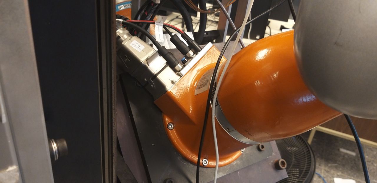
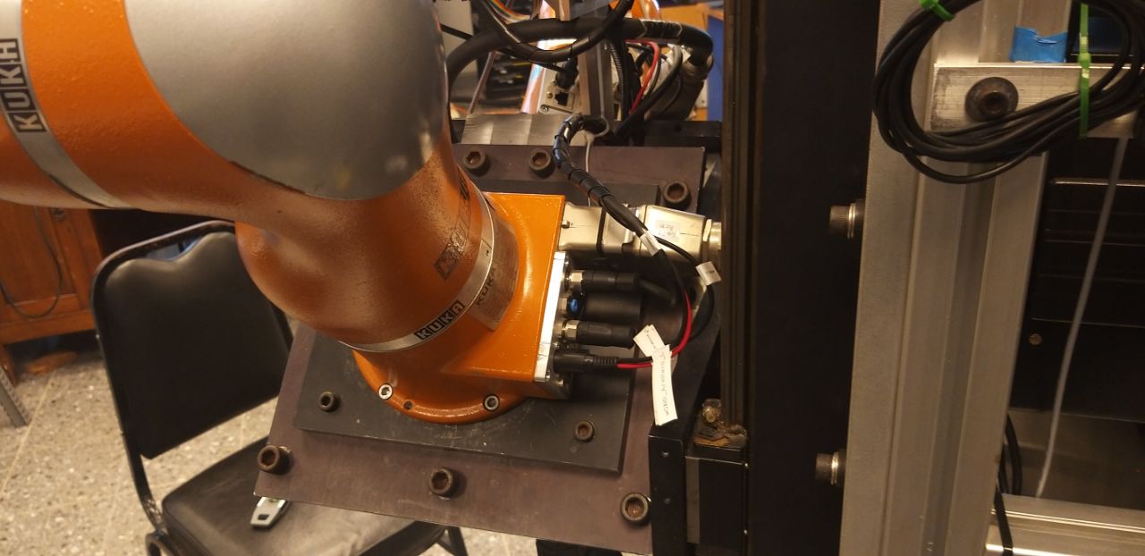
- Check the connections between the control box, the teach pendant and the robotic arm.
- On the top left corner of the controller, you will find the on/off switch. To turn in
ONrotate the switch from theOto the|. - The controller takes several minutes to power-on. Wait.
¶ How to turn them off
- Make sure that the robotic arm is not moving.
- Rotate the on/off switch in the opposite direction, from
|toO. This will start the shutdown sequence. - Wait several minutes.
- When the controller is fully off, turn off the powerstrip and disconnect the humanoid robot from the wall.
¶ How to move the robot (Spanish)
This page was originally written in spanish, we need to translate it to English
The first time you opperate the robot, you should do it under supervision.
- Es suficiente con ir a la seleción de controlador de robot.
- Esperar tres segundos.
- Seleccionar el modo de operación como aparece en la imagen, aprételo varias si es necesario, control manual con botones.
- Seleccionar el control por articulación.
- Coloque llave de acción en la posición T.
- Ya está listo para accionar el robot.
- Presione cualquiera de los botones de emergencia traseros de color blanco en la posición intermedia. Se mantiene apretado durante las siguientes instrucciones.
- El indicador I deber cambiar a color verde.
- Ahora puede mover las articulaciones del robot por control de posición.
- Si la posición del robot se encuentra totalmente estirado como aparece aquí el robot está en una singularidad, movilícelo para sacarlo de la singularidad.
- Utilice el joint A2, A3 y A5 para sacarlo de singularidad, para que quede como aparece en la imagen.
- Libere el botón trasero de emergencia.
- Seleccione el controlador del robot en Gravity Compensation.
- En el menú de configure seleccione Set Tool Base.
- Seleccione 1 y 1 para el Tool y para el Base y preciones OK.
- Presione y sostenga el botón de emergencia trasero a la mitad.
- Tenga precaución la primera vez que encienda el botón, aléjese y esté preparado para liberar el botón de emergencia en caso de movimientos abruptos del robot.
- Si el robot funciona correctamente, debería liberar los frenos y entrar en modo de compensación de gravedad.
- Ahora ud puede mover el robot con su mano libremente.
- Hay un click en el servidor y un click mas fuerte en el brazo indicando la liberación de los frenos.
¶ Advanced configuration
For more advanced configuration check the internal page.
¶ Gravity calibration
It is required to set the gravity vector to be able to use certain control modes like cartesian stiffness and gravity compensation.
Before doing a gravity adjustment, first do a mastering procedure (axis position calibration and torque zeroing calibration). For this follow the instructions on the kuka manuals. Be sure to check at the end of these calibrations that
torque_axis_actis almost zero in the arm calibration orientation. Do this calibration as carefully as possible: it will determine the quality of your gravity compensation and stiffness control.
Please check that the gravity vector is correctly configured. After you have selected the current payload (configure->set_tool/base->tool_no/base_no), go to monitor->variable->single and introduce in "name": $torque_tcp_est. Press shift-enter to have realtime variable updates. They should show small values No more than 5 Newtons in x,y or z. If they are big, this usually means, that either the payload is not properly selected, or that the gravity vector is incorrect.
To see the current gravity vector go to Monitor -> variable -> Single, once there select the $gravitation[] variable.
To edit the gravity vector you must edit the following file
c:\krc\roboter\krc/steu/mada/custom.dat
You can access that address dirtectly if you use the Windows interface of the KUKA arm. If you are using the teach pendant you can navigate by selecting the "KRC" drive at the top and then navigate to STEU->Mada->$custom.dat. In order to have access trhough the teach pendant you need to login as administrator.
There you must set the x y z components of the vector, which are at the start of the document. The vector is measured as the normal to the floor in Wold coordinates. So a floor mounted robot will have the following gravity vector x: 0, y:0, z:9.8.
You can also change the gravitation vector by accessing the monitor variable screen (monitor->variable->single), then selecting: gravitation[1] (for x) and pressing "New value" and typing the new value. For y and z use gravitation[2] and gravitation[3] respectively. When you do this, the steu/mada/$custom.dat file is updated and it doesn't need to be edited manually.
Our arms:
- Our current right arm is rotated over z 15 degrees counterclockwise and inclined to the right 45 degrees:
-
Apply Z rotation of -15 degrees (rotate arm clockwise 15 degrees to align X looking "up"
-
Apply Y rotation 45 degrees (rotate arm counterclockwise 45 degrees to aligh Z to gravity)
-
Multiply by gravity
-
KDL code for this:
g=kdl.Vector()
g[2]=9.81
r1=kdl.Rotation.Identity()
r2=kdl.Rotation.Identity()
r1.DoRotZ(-15*pi/180.0)
r2.DoRotY(45.0*pi/180.0)
print(r1*r2*g)
Right arm has X axis positive pointing out of the cables (as per manufacturer's original configuration)
- Our current left arm is rotated over Y 45 degrees counterclockwise (inclined to the right 45 degrees):
-
Apply Y rotation -45 degrees (rotate arm clockwise 45 degrees to align Z with gravity)
-
Multiply by gravity
-
KDL code for this:
g=kdl.Vector()
g[2]=9.81
r=kdl.Rotation.Identity()
r.DoRotY(-45*pi/180.0)
print(r*g)
The left arm has Y positive pointing out of the cables (90 degrees clockwise from original manufacturer's configuration)
After: 1) mastering (position and torque calibration) and 2) setting the gravitation vector correctly, without any load attached to the end-effector the torque_axis_est and torque_tcp_est should be near to zero.
If it isn't try again the calibrations.
After this you need to enter the load properties to be able to connect a hand/gripper to the arm and correctly compensate its weight.
¶ Load (hand) estimation and configuration
After the mastering and gravitation calibrations you install a load to the arm, you will get the following error:
Validate Loaddata FT 6
This means that the initial (or current) forces sensed by the arm are too high to start the arm in gravity compensation or stiffness (impedance) control.
The new attached load must be correctly estimated and entered in the kuka controller.
Errores in the force-torque 6D vector must be less than around 5N (or NM), more or less.
¶ Procedure to estimate and adjust hand load data
TODO
¶ Changing robot base position/orientation
¶ Changes in KRC
- Physically relocate the robot in the new designated place.
- Annotate or find out the new orientation information. (Translation/Rotation in X, Y and Z) (remember to annotate the order of this rotations)
- Gravitation vector points away from the earth
- Check, with cartesian jogging, the direction of the robot base axis. This will help to correctly project the gravitation vector onto those axis.
- Update the gravitation vector in file
c:\krc\roboter\krc\steu\mada\$custom.dat
- Restart and check $torque_tcp_est variable. No value should be bigger than 3 Newtons
- Consider changing the hand mounting orientation.
- If hand mounting orientation changed, update hand mass data:
- In the KRC, change to administrator privileges.
- Setup→Tool→Payload data→Tool no: 2 (hand tool), Continue
- Adjust corresponding values (mass, x, y, z)
- Restart and check $torque_tcp_est variable. No value should be bigger than 3 Newtons
- Move the robot in joint space to an appropriate initial pose. (away from table, away from joint limits, easy for table reaching)
- Open \R1\Program\FRIDemo\FRIControl.src file.
- With the cursor move to line before “PTP P6” line
- Select: Commands→Motion→PTP
- Select the correct base and hand tool frames.
- This will add the new ARM starting position.
- Erase the previous “PTP P6” line: Put cursor on this line, then: Program→Delete
- Restart KRC
- Start the FRIControl file as you normally do. Check that the initial position is as desired
¶ Changes in Linux software
Everything is now managed though the robot URDF file. Some parameters of this file depend on the Robot Body Coupler, others are ROS2 generic. Use the current file as an example for the new changes.