¶ Inkscape-Latex Circuit Drawing
This tutorial uses the modification from the Electrical symbols library shown below:

The provided .svg file contains these symbols correctly scaled and saved using Inkscape's "Symbols" feature (Shift+Ctrl+Y). To use it, follow the next steps:
¶ 0. Prerequisites
- Make sure you already have Inkscape installed on your computer.
¶ 1. Symbol Library Instalation
- Right-click the following link and select "Save link As...":
electrical_symbols.svg
If this doesn't work: Open the link in a new tab, right-click over the image, and choose "Save page As..."
- Save the file as "electrical_symbols.svg" in the directory corresponding to your operating system:
- On linux:
~/.config/inkscape/symbols - On Windows:
C:\Users\your_usersname\AppData\Roaming\inkscape\symbols - On Mac:
/Users/your_usersname/.config/inkscape/symbols
- On linux:
- Confirm the availability of symbols in a new file:
3.1. Open a new .svg file in Inkscape.
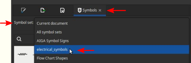
3.2. Navigate toObject > Symbols...tab or type theShift+Ctrl+Yshortcut.

3.3. Choose the "electrical_symbols" library from the "Symbol set:" option:
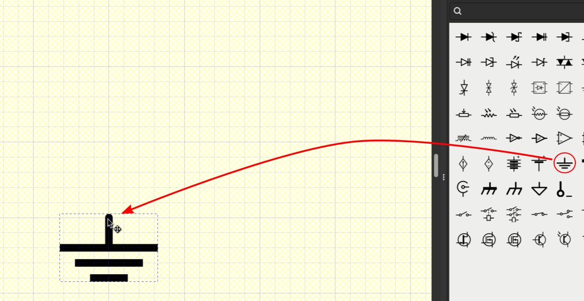
4.3.All symbols should now be visible, allowing you to drag and place them in your document.
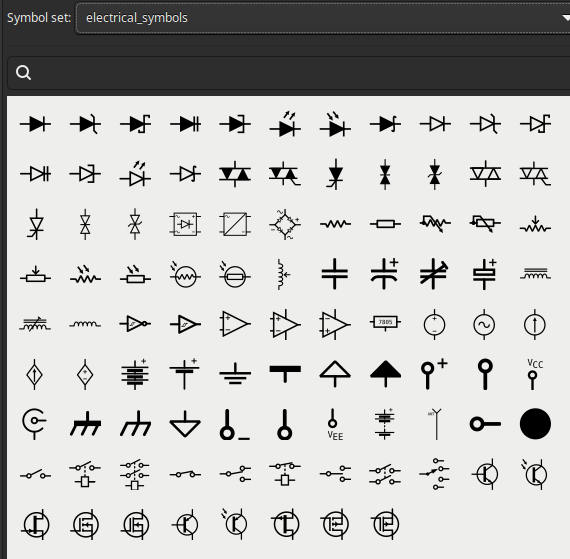
You can also search for components using the search tab within the window.
¶ 2. Grid configuration
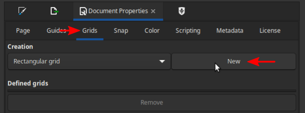
- To ensure proper alignment of library components within circuits, adjust the document's grid. Navigate to
File > Document Properties... - Select the
Gridssub-tab and create a new Rectangular Grid:
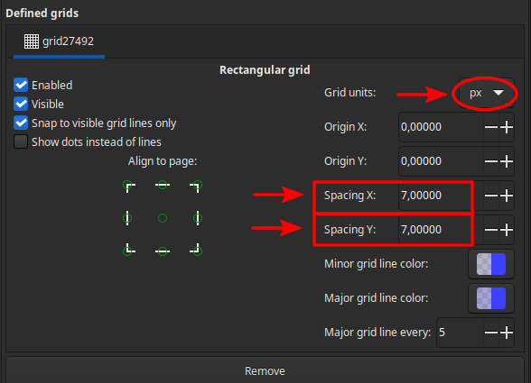
- Set both the X and Y spacing to 7px and choose your preferred grid line color.
- Save this configuration as a Template for future use whenever you need to draw circuits.
¶ 3. Circuit drawing
- Drag and place the components you need by snapping them to the grid. You can drag them from the node you want to snap.
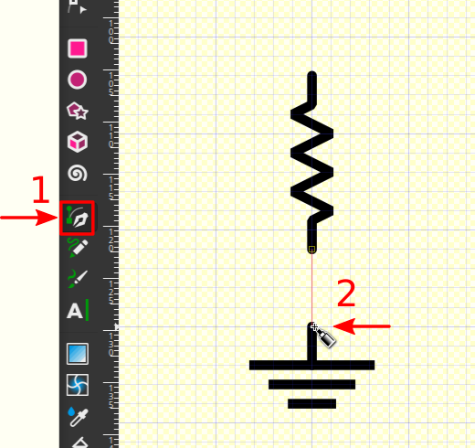
- To connect the components, first, select the "
Draw bezier curves" (B) tool from the toolbar on the left-hand side. Then, create the wire to connect them.
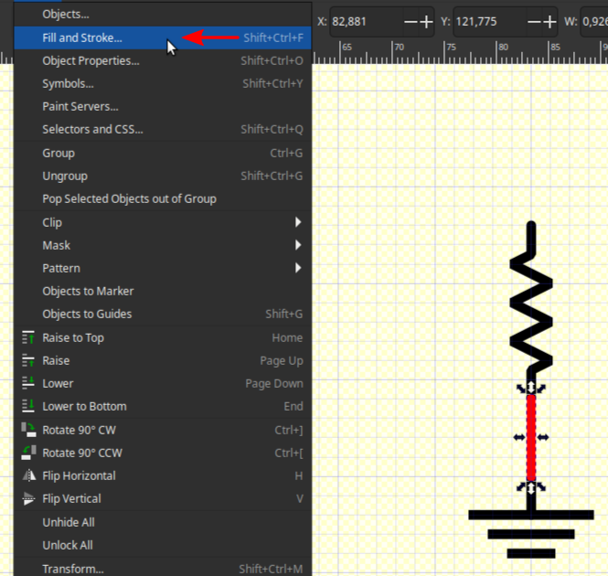
- Once the wire is selected, navigate to
Object > Fill and Stroke...in the menu.
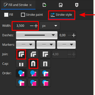
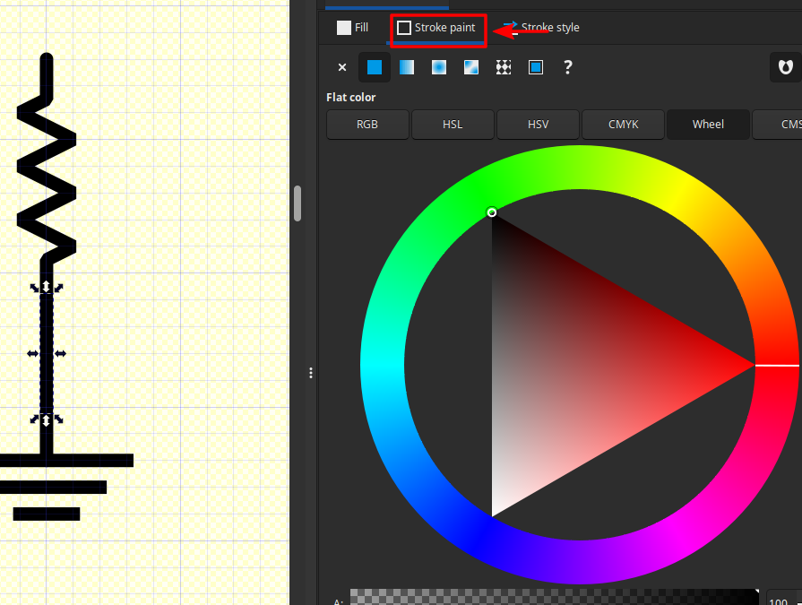
- In the "
Fill and Stroke" panel, navigate to the "Stroke Style" sub-tab. Set the width to 3.5px and choose rounded for both the join and cap options.
- Next, navigate to the "
Stroke paint" sub-tab and set the color to black.
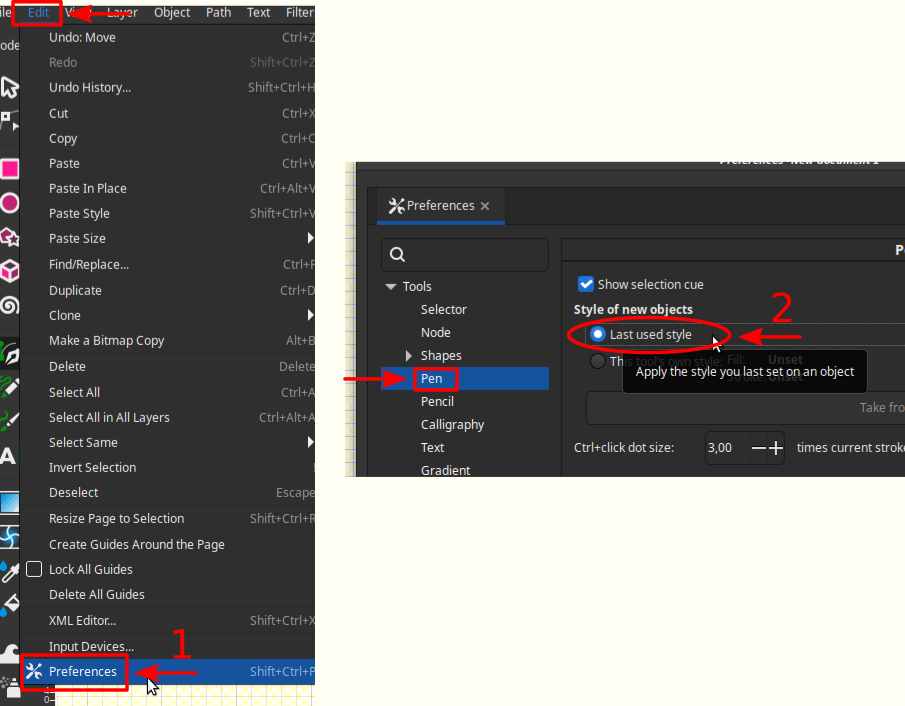
If you want to avoid configuring the wire every time you create a connection, you can go to
Edit > Preferences..., then to theShapes > Pensub-tab, and select the "Last used style" option. This will retain the settings for subsequent wire drawings.
¶ 4. Latex compilation
- With your circuit saved as an .svg file you can now follow the "Using svgs directly from .tex files" section from the next tutorial:
latex-tricks